
Industries

Telecom & Utilities

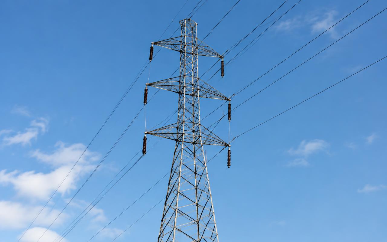
Communication towers, monopoles and utility structures detailed for fast fabrication.

Quick answer

Structural Engineering Services supports Telecom & Utilities projects worldwide with communication tower design, transmission tower design, seismic & wind load analysis, foundation design — delivered by senior engineers on licensed software to international codes.

1,200+
Projects delivered
40+
Countries served
60+
In-house engineers
2009
Engineering since

Governing codes

  • TIA-222-H
  • IS 802 / IS 875
  • EN 1993-3-1
  • ASCE 10-15
  • Operator mount specifications

Sector challenges

What makes Telecom & Utilities engineering hard

Towers are among the few structures whose loading changes every time somebody climbs them. Antennas get added, wind codes get updated, and a structure that was compliant a decade ago may not be today.

Challenge 01

Wind and ice govern everything

Antenna and mount drag, not self-weight, drives member sizes and foundation uplift.

How we answer it

Full antenna schedules are built with drag areas and mount eccentricities, then run for the code wind, ice and wind-on-ice combinations rather than a nominal allowance.
Challenge 02

Tenant loading and upgrades

New co-location requests land on towers that are already close to capacity.

How we answer it

Capacity is assessed against current and proposed antenna loading, then the lightest viable reinforcement is designed — leg strengthening, guy adjustment or added bracing — instead of defaulting to replacement.

Challenge 03

Deflection, twist and sway

Microwave links fail on rotation long before the steel is anywhere near overstressed.

How we answer it

Twist and sway are checked against the operator link criteria under serviceability wind, and stiffness is tuned where stiffness, not strength, is the controlling limit.

Challenge 04

Remote and difficult foundations

Towers go where land is cheap: poor soils, rock, rooftops and sites a large crane cannot reach.

How we answer it

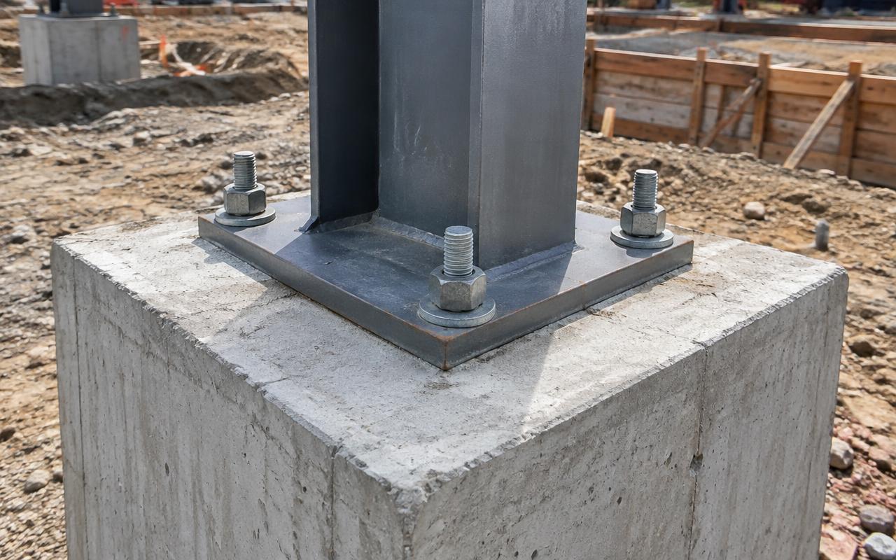
Foundation type is chosen for the site and the erection method — pad-and-chimney, piled, rock anchors or rooftop ballast — with uplift and overturning checked to the governing code.

Relevant services

Our Telecom & Utilities services

Typical assets

Structures and equipment we engineer for telecom & utilities

From a single assembly to a complete package — the asset types our telecom & utilities teams work on week to week.

Lattice telecom towers

Self-supported angular and tubular towers with member schedules and bolt lists.

Monopoles

Tapered monopoles with flange or slip joints, climbing facilities and mount details.

Guyed masts

Guyed masts with guy tension schedules, anchor blocks and initial tension setting.

Rooftop structures

Rooftop poles, frames and ballast arrangements checked against the host building.

Transmission & distribution

Lattice transmission towers, gantries and dead-end structures.

Mounts & platforms

T-arms, mounts, platforms, ladders and safety climb systems.

Codes & specifications

What governs telecom & utilities design

The base code is only half the story. On telecom & utilities work the client specification usually overrides it somewhere, so we agree a single reconciled design basis before any calculation starts.

Browse all codes
  • TIA-222-H

    US tower standard: wind and ice loading, structure class and serviceability for the link budget.

  • IS 802 / IS 875

    Indian lattice tower design and the wind loading applied to it.

  • EN 1993-3-1

    Eurocode towers and masts, including guyed mast analysis and fatigue.

  • ASCE 10-15

    Latticed steel transmission structures: bolt slip, eccentricity and member buckling rules.

  • Operator mount specifications

    Carrier standards governing attachment, climbing facilities and safety systems.

  • ACI 318 / IS 456

    Foundation and anchor design for pads, piles and guy anchor blocks.

Free quote

Not sure what you need?

Send the drawings or datasheets you already have. We will tell you what is missing and quote the scope in 24 hours.

Request a Quote

Project lifecycle

Where we plug into a telecom & utilities project

Most clients bring us in at detailed design. We can start earlier, or pick a package up mid-stream — here is what you get from us at each stage.

01

Concept & feasibility

Options, preliminary sizing and budget tonnage, before the scheme is frozen.

Site survey review, tower type selection and preliminary antenna loading.

You receive

  • Design basis memorandum
  • Preliminary weight and tonnage estimate
  • Framing concept and first-pass member sizing
  • Scheme comparison under preliminary load cases
  • Tower type and height shortlist against the coverage brief
02

FEED / basic design

Design basis, load schedules and layouts good enough to price and procure from.

Full antenna schedule, structure sizing and estimated foundation reactions.

You receive

  • Load schedule and design criteria
  • GA drawings good enough to price
  • Connection philosophy and tonnage take-off
  • Governing load combinations fixed per code
  • Antenna, feeder and mount loading schedule
03

Detailed design

Full analysis, code checks, 3D modelling and issued-for-construction documentation.

Analysis, member and connection design, detailing with bolt lists and erection marks.

You receive

  • Checked design calculation report
  • Issued-for-construction drawing set
  • LOD 400 Tekla model with shop and erection drawings
  • Member, connection and foundation design sheets
  • Signed structural capacity assessment report
04

Fabrication & site support

Shop queries, RFIs and as-built updates while steel is being cut and erected.

Fabrication queries, site modification details and post-installation mark-ups.

You receive

  • RFI and technical query log
  • As-built red-line mark-ups
  • NC/DSTV files and shop fit-up support
  • Field-change re-checks and repair calculations
  • Reinforcement and site modification details

Deliverables & handover

What you actually receive

Tower scope includes the capacity assessment as a standalone, signed report, because that is the document filed with the site owner and quoted in the next co-location application.

DeliverableFormatIssued at
Design basis and calculation reportPDF, signed and checkedDetailed design
General arrangement drawingsDWG + PDFFEED to detailed design
Drawing register and transmittalXLSX + PDFEvery issue
Tekla 3D modelNative .db1 + IFC 2x3/4Detailed design
Single-part, assembly and erection drawingsPDF + DWG, one sheet per markDetailed design
CNC files, bolt list and BOQNC1/DSTV, DXF, XLSXPre-fabrication
Analysis model and load combinationsSTAAD .std + PDF summaryDetailed design
Connection and base-plate design sheetsPDF calculation packDetailed design
Antenna loading schedule and capacity assessmentXLSX + signed PDF reportAll stages
Tower reinforcement and modification detailsDWG + PDFDetailed design

Two-stage check

Originator, then senior checker signs off every sheet before it leaves our office.

Native files included

You own the model, so another team can pick the work up at any point.

Revision control

A revision table on every sheet; superseded issues are archived, never deleted.

Your transmittal route

Issued through your document-control portal with your numbering, or over secure FTP.

Directory

Telecom & Utilities engineering by market

Jump straight to the market you build in. Every page sets out the governing codes, units and delivery window we work to there.

8 markets

Start your project

Send your drawings. Get a quote in 24 hours.

Free, no-obligation proposal from a senior engineer.

Request a Quote
irPowered by IRPR